onsdag den 31. august 2016

Black Snapper L Pro - build log part 1

Hey there,

time again to write a little about a new project of mine. Lately I have bought a Black Snapper L Pro frame from Globe Flight.

(Bought it several weeks ago; Now they have an updated version with "service flaps" for easier access of in-frame-mounted electronics. But when you have the dampened battery plate, these won't be accessible anyway. As far as I can tell from the pictures)

The target is to get an up-to-date long flight (+20 minutes) multirotor plattform for light aerial tasks (carry GoPro, Sensors or other payload with several hundred grams of weight).

As always there was the question of components.

Naturally you need the frame. I bought:

  • the basic main part
  • dampened battery plate
  • red glass fiber base plate
  • GPS mast

And that is it.

I haven't ordered a landing gear as my Fabikator Mini 3D printer is sufficient in build space to print some. But this will follow in another posting.

With any frame the first question is where to mount the components:

Of course the ESCs will go to the designated mounting positions suggested from Globe Flight. Otherwise the folding arms of the copter would most probably not be foldable any more. 

GPS mast has also designated mounting position and holes. 

Battery will be strapped to dampened mounting plate. 

Motors go to the mounts at the outer end of the arms (what a surprise!)

For the RX I don't have a final solution yet. But time will deliver a solution. 

The last two remaining parts are a Flight Controller and the power distribution from the battery.

For the power distribution I have bought a power distribution board from a popular market place
This will be mounted with two 3D printed adapters to already existing mounting holes in the frames base plate. As I am using a Pixhawk and I also have a spare voltage/current sensor for the Pixhawk available, this Sensor will also be fastened be this PDB mount.
The STL-files for this mounting adapter are attached here.

Link to mounting adapters

The result of the PDB and Pixhawk Sensor mounted with the printed mounting bars is shown in the following picture.

Mounting bars with PixHawk current sensor below

Mounting bars with PDB attached

I have added a strip of double sided sticky silicone tape between with sensor and the red base plate. Also I strapped the sensor down with a zip tie. You can see a small part of the zip tie in the second picture.

The last part in this listing missing is the Flight Controller. 
This frame is not intended to be used with a Pixhawk. Sadly Globe Flight has only a solution for DJI parts (DJI Naza). So again there is a custom mounting required. 
As already done by my S900 build, I wanted the FC to be mounted with a vibration dampening. So I bought an of the shelf APM vibration dampening mount, used the dampening rubbers and the bigger base plate and printed some custom mountings for already existing mounting holes in the frame's side walls. 
The result is shown in the following picture.

PixHawk mounted to Snapper


The according STL-files for the mounting arms can be found here:

Link to PixHawk mounting adapters

That's it for the time being.
Next steps will be to think about and realize a position lighting system to the Snapper. For this I am thinking about pos lights at the end of the Snapper's arms and a lighting control via a personalized rebuilt of the JD-IOBoard (Store link;  GitHub link).

But this will be part of another post soon.

All the best
Sebastian

onsdag den 6. april 2016

Analyzing Sony's Multiport - Part 4

Hi again

It has been quite some time since my last post to Sony's Multiport. Sorry for the delay.
But I have some new findings for Protocol and some more tips for an alternative solution than mimicing the Multiport protocol. But more on that later.

Off to the new finding about Sony's Multiport serial protocol.
It is not very relevant for decoding the data and finding out how to control the functionalities, but it can help debugging if errors might occur.

Maybe you remeber the pictures from analyzing the serial data setup from part 3 of this series.

In the end we were recognizing that Sony is most probably using a 9600 Baud serial communication with a bit setup of: 1 Startbit - 8 Databits - 1 even Paritybit - 2 Stopbits.

The corresponding picture was the following:


This picture was from pin number 8 (serial TX) of Sony's Multiport connector. But we know there is another pin with communication. Pin 9 (serial RX).
Now I started analyzing a serial message of pin number 9 which looks like the following:


As you can see, my scope was again off with timing/packets for direct analyzation of serial data.

So when we zoom the data and add identical timing bars from the analyzation session of TX pin, we can see the following:


At the end of transmission the timing bars end, but not the bits that are transmitted!
Quoting Homer J. Simpson: Doh!

But there is no reasons for despair ;)
Having a closer look into the transmitted data (the rising and falling bit flanks) and the timing bars, you can recognize that the timing bars for the single bits are way off on some parts.


Well it is quite normal that serial transmission can be off with their timing (too short, or too wide bit timings due to bad clock, a lot of other tasks for the microcontroller, sun stroms, hickups in space time, annomalies in subspace, ...  pick your reason ;) ).
The trick in a serial transmission is normally: Every new data-block is "synced" fresh at its own starting bit.
So an error in a serial transmission doesn't sum up over a longer series of messages. Instead a timing error is only relevant for each single data packet. At least when timing is not off more than:

T_bit = T_bitexact -5.56% / +6.25% 

So I tried to allign the timing bars new for each data packet and set off for finding the edges of data packet one. I Found the startbit, 8 data bits, the matching even parity, and last but not least ....
well maybe you guessed it already: There were not 2 stop bits as expected!

But to keep in order of my analyzation process:
The stream at the the end of a data packet 'started' as expected with one logic bitvalue at 3.3V, but after that I found a logic bitvalue of 0V instead of a second bit with 3.3V.
Hmmmm......
To use a quite famous acronym you find all over the web: WTF?! Oo

I was quite puzzled to not find the serial bit layout I priorly analyzed at the serial TX pin of my camera (pin 8 - UART_TX). So I checked the complete bit stream and found that Sony obviously is using a different serial bit layout on pin 9 (UART_RX) than they are on pin 8!
Yes you have read correctly:

Serial bit layout on pin 9 is as follows:   start, d0, d1, d2, d3, d4, d5, d6, d7, parity, stop

Don't believe me? Check for yourself at the following picture:


What a baffling finding! What a bunch of sly foxes at Sony that try to bamboozle honest and hard working reengineering RC enthusiats ;)

So again a new part in this puzzle to analyze Sony's Multiport and try to reengineer the communication for an <AddYourFavoriteMicrocontrollerHere>-remote.

Let's again sum up what we know up to this point:

Hardware signals:
  1. Trigger of autofocus function via shorting pin 11 to ground (="half press"; works both in photo mode and while recording video)
  1. Trigger photo (= full press) via:
    1. FIRST triggering AF function (shorting pin 11 to ground)
    2. Shorting pin 12 to ground directly afterwards or better while shorting pin 11 to ground (my camera is NOT taking a photo when only pin 12 is shorted to ground!)
  1. Switching camera on/off via shorting pin 15 to ground (only when the main power switch at photo button is priorly set to 'on'). Helps saving power when camera not needed.
  1. Camera is responding on serial port (pin 8) when connecting pin 10 via a 'x' kOhm resistor to ground (for A6000, response has been seen with value of 100kOhm). 

Communication signals (Serial lines):
  1. pin 8 (UART_TX) and pin 9 (UART_RX) are for serial signaling
  2. Pin 8 is using a 9600 Baud serial transmission with a bit layout of: 1 start bit, 8 data bits, 1 even parity bit and 2 stop bits
  3. Pin 9 is using a 9600 Baud serial transmission with a bit layout of: 1 start bit, 8 data bits, 1 even parity bit and 1 stop bit
For the baud rate I'm a bit unsure at the moment. I am convinced on serial rx line the baud rate must be a bit less than on tx line. But I will have to recalculate this.

So that is it until now for Multiport serial protocol layout.

With the tips of Jörgen in the comments of my last two posts I will hopefully find out something more about the serial contents in the near future.

Now to the last bit I learned shortly:
Linux has a library and according software for communicating and controlling a lot of cameras via a USB connection. This amazing project is called "GPhoto" and is located here.
also Sonys "Alpha" mirrorless cameras are included in this library and there seems to be quite some functionality remote controllable. But I haven't tried myself yet.
So there may be a faster or at least alternative way then reengineering Multiport. Using a (small) linux box and controlling the A6000 via USB.
This approach would have some benfits and some drawbacks. but that has to be investigated sometime else.

Hope you like the analyzation of the Multiport protocol and you will stay tuned.
If I had more time I would also write you more about my new gimbal setup (DYS NEX gimbal style) with a brand new "Storm32 NT" gimbal control board and "NT IMUs". Really great setup! Circumventing a lot of issues with I2C gimbal remotes!
And I would write you something about my new "Fabrikator Mini v1.5" 3D printer used for the IMU cases, the bimal mounts and many things more.
But that will hopefully be another story ;)

All the best to you all!

søndag den 20. marts 2016

DYS BL16A Speed Controller ESC SimonK/BLHELI Firmware

Speed Controller ESC SimonK/BLHELI Firmware

Ordered this unit to go with the Le Todar 2204 - 2300KV, but again rather than buying a stack and finding out that that quality was useless, i ordered a single. They are different models available depending on the amperage needed. Here are the different versions available according to the provided manual.


When the package arrived i was pretty amazed at the size of the ESC, This is tiny compared to a standard 20-30A ESC, this unit can easily be nicely tucked away on a QAV250 rig.

 The unit is delivered without connectors, so you will need to purchase some banana plugs, I reckon a 2mm or a 2,5mm plug will be ok for this ESC. I only had 3mm lying around so i used these and they are maybe larger than i wanted. Solder the three black wires with banana plugs and heatshrink the plugs after soldering.

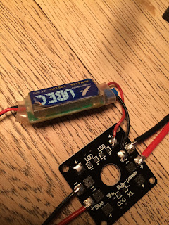
 I used a CC3D Quadcopter LED Power Distribution Board to mount the positive and negative wires from the ESC


 I soldered two wires for the main power supply from my LIPO battery, you will need to of coarse mount the end with your favourite connector, Deans, XT60 or whatever you prefer, might sound silly but i have ade this simple mistake a few times, check your polarity and make sure it is not reversed + with + and - with -, sometimes one is so focused on other things, that these simple tasks tend to go wrong.

 These ESC's are OPTO versions and do not provide a 5v from the ESC to power external units like your flight controller, so you will need a UBEC mounted on the distribution board that can provide the needed 5v power

Connect the motor wires to the ESC


 Connect the signal wire from the ESC to the servo tester, the white cable is the signal wire. Connect the 5v to the servo tester again remember to check your polarity.


Connect your battery, and the servo tester should initiate, now you are ready to test your ESC and motor. You might have to manually calibrate your ESC to get the full range of the servo tester.

This ESC is programmable using DYS ESC USB Linker Programmer
 
Her are some of the options that can be programmed. I have not yet purchased the programmer, so will not talk too much about this.You can watch this video.


lørdag den 12. marts 2016

Le Todar 2204 - 2300KV for QAV250

Le Todar 2204 2300KV

I decided that I wanted to build a QAV250 drone, I did some research on Ebay for the different parts needed, but as usual there are many options available, but little or no information or test data that confirms if a product has the desired quality.

The Le Todar 2204 2300KV Motor for Mini 250mm QAV250 QuadCopter Aircraft FPV looked to be an intresting choice but rather than ordering a set of 4 and being disappointed if the product was of a cheap quality, I ordered a single motor for reviewing.

These motors are  purchased at $6.69 plus $2.20 for shipping and shipped from China. Other motors of the same caliber are sold from Hobbyking at around $12-14, so a good price if these motors hold up.

These motors are supposably a rebranded MRM mini Titan solded at a whopping $26. Firstly look at the images and you will notice a striking resemblance, these two products look very identical. But again i have no evidence to prove my case.


Le Todar 2204 - 2300KV                        MRM Mini Titan V1 2204/2300kv Brushless motor

If we look at the bottom bearing the two products look identical, they have an oversized bearing and both have a 5mm hollow shaft to save weight


Other features of this motor are as follows;
Interchangeable propeller adapter for both traditional propeller and thin CF propeller
Flat motor base eliminate the need of shaft hole on any motor mount this motor comes with a countersunk c-clip, so you can mount it to any flat surface. Doesn't need a hole or x-mount

Bearings are 5x9x3 (MR95ZZ). 

490g of thrust with HQ 5x4 at 10.5A / 130W !  

Bolt on style prop - 2 styles  spinner and 2 blade CF adapter included
Shalf: M5

Bottom mounting Holes : 16mm*19mm 3m

Weight 21 grams
Compared to a propdrive 28-26s 1100 

The quality and the finish is of the Ebay Le Todar is actually very good and am looking forward to testing these motors. Tested this motor running a 3s 4000maH battery on a 30 simonK 30A esc, did not have a smaller ESC, so to avoid destroying the ESC i ran it at low RPMs, apart from resonance from the wooden surface, these moters are very quiet, run very smooth and plenty of punch, looks like the bearings are pretty solid on this unit, wow i am looking forward to putting these into action.

onsdag den 24. februar 2016

Carbon Fiber REPTILE X-Mode Alien 500 500mm Multicopter Quadcopter Frame Kit

A quick look at the Reptile X-mode Alien 500 quadcopter frame. The frame arrived nicely packed with the appropriate  screws, a battery strap and a mounting plate for a front faced camera and 4 vibration pads for the camera mounting plate. There is no manual with the shipment, so mounting is done by guess work. A very nice light frame, very easy to assemble, 


 The top and the bottom plate.

The arms are easily mounted on the top plate using four screws.


 I did not tighten the screws entirely until the bottom plate was mounted

 The CC3D was mounted on a CC3D Atom Flight Controller Anti-Vibration Damper Shock, this damper is a little too tall to fit under the hood as the wiring becomes an issue. The header pins from the ESC's were not able to fit without bending. I ended up removing the housing of the header pins and isolating each cable with heat shrink and mounting each signal cable on the CC3D.


 The dampening plate was mounted using plastic screws, these are of coarse not supplied, so you need to have hese lying around

 Very little space between the top plate and the CC3D header pins if you use the

 The bottom plate is mounted using two screws on each arm.


 The rig is very light, with only the flight controller mounted, it checks in 346 grams.


 The motors fit on the mount arms with no hassle, I did find the Hobbykings NTM 28-26 1100 motors had to be turned 90 degrees to mount all 4 screws. This meant that the wiring from the motors stuck out sideways, whilst the Sunnysky motors could be mounted so the wiring was parallel to the arm.


 A normal sized ESC fits  very neatly on the arm.

 A word of advice, always REMOVE your props when testing indoors, once again i failed to adhere to this and ended up cutting up my fingers on the props, while configuering the quad.

 What to do, if you don´t have any plaster to take care of your injuries. Gaffa tape and toilet paper can also take care of things.
i will post a few more photos of the finished product

Mounted a red LED lighton the right side for orientation purposes and a blue on the left


 The carriage is mounted with a white LED

 The battery is strapped down on top of the frame

The reciever is mounted with velcro to keep it from moving around


søndag den 7. februar 2016

Analyzing Sony's Multiport - Part 3

Hi

Here is the third post with some updated information to the Multiport protocol used in most of Sony's (photo) camera's since 2014.
This time I grabbed one of the data streams I priorly captured with my DSO and tried to find some patterns.

I started with the following data stream:


To start the analysis I tried to not take any priorly known knowledge for settled. The only properties of this data stream I took into account were:

  • It must be a serial protocol!
  • There should be a start bit for syncing.
  • There must be some data bits (commonly 8)
  • There could be a parity bit or no parity bit.
  • There could be one to 'x' stop bits (regularly 1, 1.5 or 2 bits)
So what to do at the beginning? Trying to find a bit width should be a good start. An from post number 1 in this series, combined with the assumption that the max bitlength can be seen at possible start bit, I added timing bars to the above data stream. The result looks like this:


I also added a count of the single bits to the timing bars in the above picture. As you can see, there are at least 69 completly identifiable bits. And possibly some more at the end of the data stream. 

With the above picture I tried to make an educated guess and marked the start bits in the whole stream. With the first bit as a "0V" sign, I assumed that there are only possible start bit with a "low" value. 
With the assumption that you have a start bit and 8 guessed following data bits, I marked the bits in the picture as follows:


As you can see with the first assumed byte in the above picture I marked the data as follows:

  1. Startbit as '0v' (low)
  2. 8 Databits
  3. some other bits (3 as you can see)
And this was my first finding. It seems the serial protocol has the form of: "1 start-bit; 8 data-bits; 3 other-bits". 
So in the end I assume there are 12 bits per transmitted data-byte. 
With this knowledge I finalyzed the timing bars as in the following picture (added some at the end to finish the stream):


As you can see at the end of the data frames I added bits 71 and 72. 
So in the end in the analyzed data stream you have 6 bytes (8 data-bits) with each possesing one start-bit and 3 'other'-bits. In total 72 bits.

Now the only thing unknown are these 3 'other' bits in each packet. 
The possible reasons for bits after the data-bits in a serial stream are 'parity'-bits and 'stop'-bits.
As the parity information is always one bit, we can check if the first of the 'other'-bits is changing and if there is a pattern related to the prior data bits. And the finding is, that in data packet 3 and 4 you have different bit values for the assumed parity, compared to in data packets 0, 1, 2 and 5. So we can assume this is a parity bit at last. 
This leaves the last two bits in the several data packets without a property. And the only rational use for these last two bits are to be 'stop'-bits.

The only thing we need to figure out is, if the parity bit is of 'even' or 'odd' style. To answer this question, we only need to perform a 'XOR' operation over all 8 data bits within a packet and compare the calculated 'Xored' bit with the value of the assumed parity bit. Doing this with the first packet, we find the following:

First packet is:    start, 1, 1, 0, 0, 0, 1, 0, 0, parity, stop, stop

We need to perform the following calculation: 1 xor 1 xor 0 xor 0 xor 0 xor 1 xor 0 xor 0 = 1

As the parity bit in this packet is also '1', we can assume we have an even parity bit. 
If we apply this finding to the other data packets, we can confirm that even party is also applied in the remaining packages.


So to summarize our findings at the end we are now assuming the following:
  1. Sony's multiport protocol is a serial protocol with two serial data lines (at A6000 camera: pin 8: UART_TX; pin 9: UART_RX)
  2. Serial speed is 9600 Baud
  3. Serial data setup is: 1 Start-Bit, 8 Data-Bits, 1 Parity-Bit (even), 2 Stop-Bits => 8E2
We don't know anything about the sent and received data yet, that is controlling the camera and signaling the camera states. But I hope there is more knowledge to come. 

So as final words:
Please don't give anything on the data shown in the scope pictures I posted in the prior posts one and two, as I configured the scope for 8N1 decoding in these screenshots.