You can see the partly finished product in action her
You need to purchase this LED controller off of Ebay, they cost a mere 5 dollars
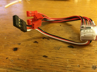
LED Light Strip Controller
The unit consists of a balancer male housing for the connecting the battery balancer plug for powering the unit with the required amount of power. It has four JST plugs for connecting the LED strips and a header pin wire for connecting the unit to your transmitter.
They are available for different battery cells, I have 3S batteries, so the link corresponds to my battery type.
You will need some 12 volt LED Strips. They are purchased in different lengths and colours. Note: There are two versions, a non-waterproof and a waterproof version. The waterproof version is a bit harder to work with as i requires that you remove/cut the rubber lining protecting the LED from getting moist. Cut a strip corresponding to the lenth needed. You need to cut it just before the copper pad as you need to solder your 12 volts power here.
Grab a sharp hobby knife and gently cut a groove in the rubber lining, be careful not to cut too deep, as you might damage the copper pad and render the strip useless.
Put a bit of solder on the pads
Solder the positive and GND wire , pay attention to polarity, red goes on the line that says +12v
once you are cover the wiring with some heat shrink.

I only used two LED stripes as i am still waiting for another colour to arrive so i can mount the last two stripes.

You can then test your unit by simply plugging the balancer plug into the unit and it should light up. But we more to do as we need to be able to change the lighting modes via the transmitter.

Plug the signal wire into a spare channel on your receiver, mine was plugged into channel 7.
I have a Tarnis plus, so i created a logical switch called L17, that defines the SD up button, L18 defines the middle SD button, L19 is not necessary as we are only using the up and middle button to change the mode, nevertheless it is there, but not in use.

On your receiver create two mixes, that correspond to the channel you plugged the header pin in the receiver. Notice the weight has been set to 41, the weight determines how fast the lights blink in the first blink sequence. Assign L17 in source and switch is set to SD up, my setup reads L16, so need to change that. The second mix under channel 7 should be set to source L18 and SD middle.
The mix should look like this. Power up the multi rotor and have the balancer plug in the Strip controller, flick SD in the middle position. The lights should start to blink, and the mode changes every time you flick the switch. I am no expert on radios so they could be an easier and simpler method of setting up the mix, so let me know if you do it differently.


