I decided to try out the option of using a power distribution board I had lying around, this mounts directly under the frame and tightened down with two plastic screws that I ten used to mount the flight controller.
Mounted the flight controller in X configuration.
I soldered a wire from the 12volts for the voltage alarm on the KK2 board
Mounted the wire on the KK2 board, that gives me an alarm when the battery is getting close to depleted.
I later came to realize that the polarity was swiched around, the + is on the right, closest to the edge of the board.
Notice the + is on the right, not the left, I realized this when double checking my wiring. One thing to do is always run through all the cabling that you have soldered or changed. One simple mistake will give you white smoke and a bill for replacement parts.
I then soldered banana plugs on the ESC's + and - so I could connect them directly to the power board.
Put some shrink tube on the wiring to avoid shorting.
Connected the ESC's to the power distribution board.
Again remember to check your polarity, you can always use a multimeter to check out the voltage and the polarity before connecting the ESC' s
Zip tied the ESC's around the arm.
Shortened the wiring on the other end of the ESC's, shrink wrapped it.
Zip tied all the cabling along the arm. Put all three cables through a shrink tube, was not really necessary, but helps keep it neat and tidy.
Soldered a XT60 plug on the cable that comes from the distribution board. Again remrmber to check your polarity, trust me been there, a mistake here is fatal for your rig.
Forgot the power for the KK2 board, soldered a UBEC on to the 12 volts on the PDB
Split the output of the UBEC, making two power sources, one for the KK2 board, the other for the Orange Rx radio receiver.
Powered the KK2 board on pin 1 of the motor connectors, +5v is the middle rail and the - rail is on the bottom. The top rail is the signal from the motors.
The other end of the UBEC I connected to Orange RX reciever. I plugged it into Batt/Bind, the middle is the 5v+ and the bottom is the negative. The top is not used.
Plugged 3 pin servo cable into the throttle slot with only one wire attached in the top row for the signal.
This corresponds with pin 3 from the top of the KK2 board. The top is where the white arrow is.
The cables are mounted in the signal rail or the top row, that being the row closest to the middle.
Pin two on the RX receiver Aileron corresponds with pin 1 on the KK2 board
Elevation on the Rx receiver corresponds with pin2 and rudder sits on pin 4 on the KK2 board
Connected the aux channel on the Rx receiver to pin 5 on the KK2, this can if programmed on your radio, be used to control the selv levelling feature of the KK2 board.
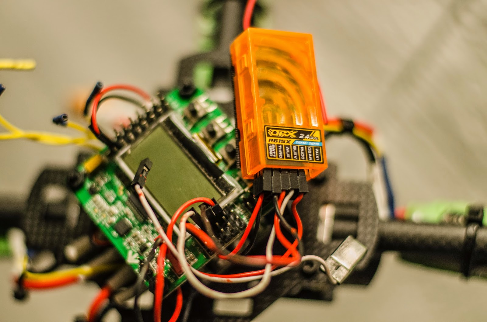
Zip tied the Rx receiver on the arm of the quadcopter.
I thought of an idea I wanted to see if works. The mounts of this frame don't look too rigid and I feared a crash will probably cause damage to my motors. I would prefer to use normal mounts but needed a way to customize them.
I mounted all the alu mounts on the four arms all facing the same direction, the motors are off centre, but i reckon the result will be the same, the pull and thrust on the frame should be equal. Might require some offset adjustments.
Mounted the motors and zip tied the cable along the arm for a neat finish.
The quad weighs an astonishing 717 grams without the battery mounted, this will surely give me a good flight time.
Mounted with a Zippy 4000 20c battery the weight crawls up to 1048 grams.
Not done yet, we need to configure the KK2 board and mount the signal wiring from the motors
Check your cabling before plugging in your battey. Once checked plug in your battery. The KK2 should fire up. Using the 4 buttons at the bottom navigate down to "Load motor layout".
Choose Quadcopter X mode.
Yes you are sure.
This gives you the motor layout. motor 1 signal goes to pin 1 on top of the power cable we previously plugged in the KK2 board. Motor 2 on pin 2 and so on. Remember the motor direction as well, jot it down on a small paper, you will need to alter it later on. If you don´t have paper you can always check the configuration using the KK2 board
Exit back to the menu and move up in the menu to receiver test.
You should see your receiver settings. You need to trim your radio to get Aileron/Elevator/Rudder to 0, you can move the sticks on the radio and check if your setup is correct. If you move the throttle stick up, the corresponding throttle on the KK2 board moves up and so on.
Trim your radio using the Trim buttons to get the settings on the KK2 board to 0
Once trimmed all settings should be Zero, you can also flip your switch that you programmed to check if it works.
You need to calibrate your accelometer, navigate back to the main menu find ACC calibration.
Put your quad on a level surface.
System calibration taking place.
All done
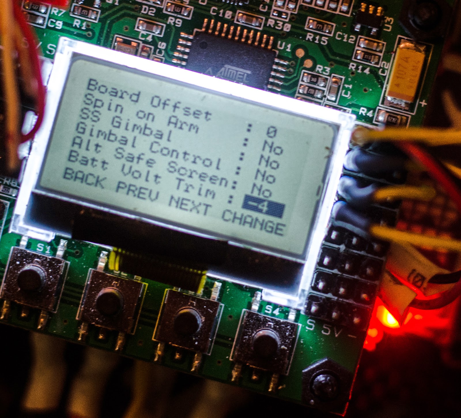
Another options available on the KK2 board is the selv-level under mode
You can if you have programmed your radio, use a switch to activate and deactivate self-level. Otherwise you can change this setting to always on. The KK2 board will power up with self-level on
Other options include setting your battery alarm under the menu option misc. settings 1, mine is set to beep at 10.6 volts
You can trim the battery if it displays the wrong value on the the on-screen display, this is done under misc settings 2.
If in doubt, you can check if all the sensors are working correctly.
all good!!!
There are a number of options like tuning the PIDs for better flight characteristics but will get into that later.
The finished product.
The motor mounts all facing the same direction, and it does initially take off, but might need some offset trimming.
Well not bad for a couple of hours work. Time to fly....
Well after a couple of flights with this frame, I thought I would give my views on it. All in all the frame is very light and stabil frame, flying was very easy and due to the light weight it gave good flight times. It maneuvers nicely and quickly.
Pros: The motor mounts tend to give way on landings, turning the motor just enough to unbalance it, this means that you have to center the motor once in a while when it starts to yaw. I tightened the bolt holding the mount, but did no good. I noticed that the mount is working its self into the carbon fiber tubing and slowly wearing it away. This will eventually become an issue as it will require a new tube. I have considered ordering a 12mm motor mount off ebay to use instead and moving the landing gear further inwards, loosening them a tad, so that they can give way if they endure a heavy landing, thus not wearing the tube.
After 4-5 flights without crashing the mount wears the carbon tube

My new plan is to move the landing gear further down the tube, loosen them a bit so they can give way and mount an extra 12mm alu motor mount at the end of the tube, this way the motor will be more stable.


Ingen kommentarer:
Send en kommentar